Deeds - Microcomputer Systems
(Hardware description)
Micro Computer Component (Basic)
Micro Computer Component (Enhanced)
 Micro Computer Component (Basic)
 Deeds-DcS Symbol
The basic Microcomputer is a component of the Deeds-DcS tool, and can be configured with different types of CPUs and the desired amount of ROM and RAM. The configuration is obtained by loading the specific project into the component. The project must be defined previously using the Deeds-McE tool.

This system provides 4 input ports, 4 output ports and one interrupt line.
Architecture
The architecture of the Basic Microcomputer is described in the figure below. In addition to the elements of the CPU, ROM and RAM (configurable at design time using the Deeds-McE tool), it includes a programmable Clock Generator and a timed Reset Generator.
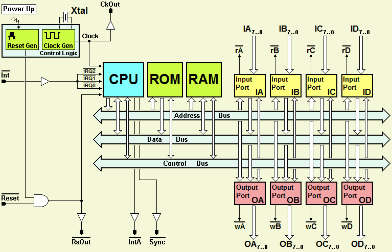
The common bus is not accessible from the outside. However, 4 input ports and 4 parallel output ports are available, providing a total of 32 input and 32 output lines. Moreover, each port has a strobe signal, useful for creating complex ports around the basic structure.
Micro Computer Component (Enhanced)
Deeds-DcS Symbol
The Extended Microcomputer is also a component of the Deeds-DcS tool and can be configured with different types of CPUs and the desired amount of ROM and RAM. Again, the configuration is achieved by loading the specific project into the component. The project must be defined previously using the Deeds-McE tool.
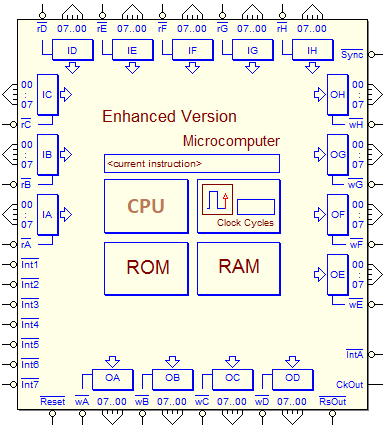
8 input ports and 8 parallel output ports are available.
The peculiar feature of this component is the presence of seven vectorized interrupt lines, which allow you to practice programming interrupt-based systems.
Architecture
The architecture of the Enhanced Microcomputer is visible below. Like the Basic version, in addition to the elements of the CPU, ROM and RAM, it includes a programmable Clock Generator and a timed Reset Generator.
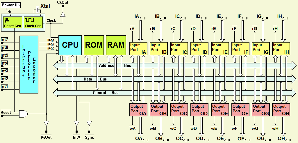
Also in this component the common bus is not accessible from the outside. 8 input ports and 8 parallel output ports are available, for a total of 64 input lines and 64 output lines. Also in this case, each port has a strobe signal, useful for creating complex ports around the basic structure.
As shown in the figure, the seven interrupt lines are routed to the processor via a priority code. The Int7 line has the highest priority.
...To be completed... 
Micro Computer Input/Output Port
Input Ports
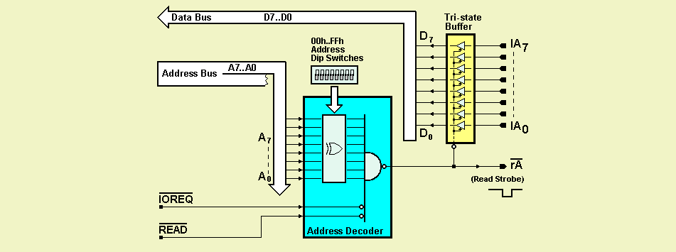
In the figure below we see the basic diagram of the IA input port. The other ports are identical. During the configuration at design time we can assign it a specific address (among 256 possible). The rA Strobe line is activated when the processor reads the data from lines IA7..IA0.
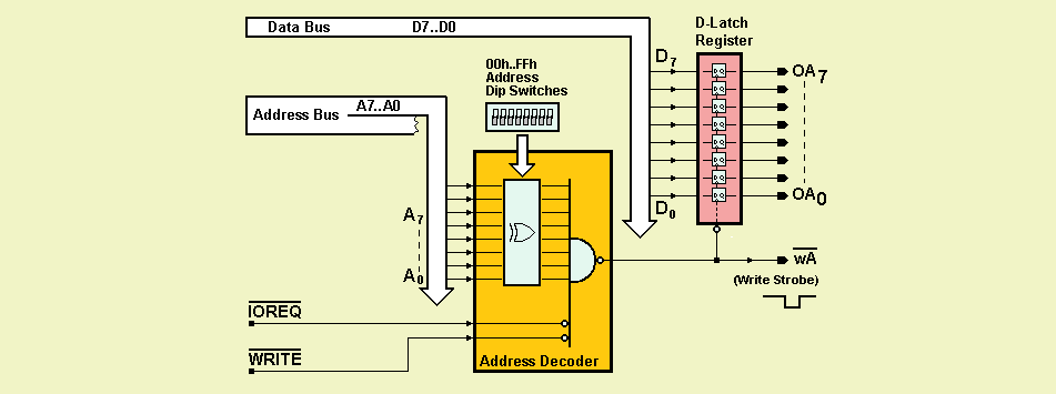
Output Ports
The basic schematic of the OA output port is shown below. All other output ports are identical. The address to which the port responds (of 256 possible) is assigned at design time. The Strobe line wA is activated when the processor writes data to the register, making it available on the OA7..OA0 lines.
Interrupt System Configuration
Interrupt System Choice
...To be completed...