Flip-Flop-Based Synchronous Networks
6.1 Synchronous and Asynchronous Signals
6.1.1 Synchronizer
6.1.2 Multistage Synchronization
6.2 Registers
6.2.1 Parallel Registers
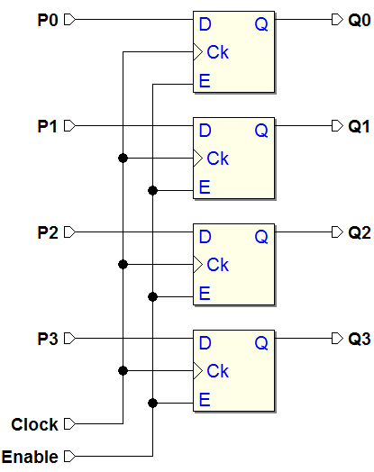
Eight bits Parallel Registers, from the component library of Deeds
6.2.2 Shift Registers
Using D-PET Flip-flops
Using E-PET Flip-flops
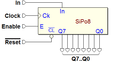
S.I.P.O. Registers, from the component library of Deeds
6.2.3 Shift Registers with Parallel Load
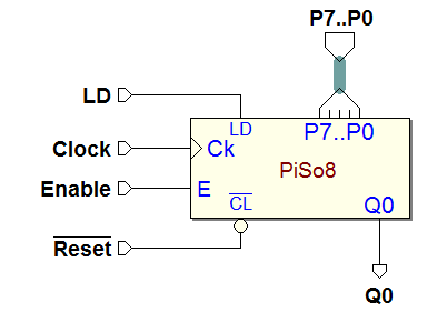
P.I.S.O. Registers, from the component library of Deeds
6.2.4 Universal Shift Register
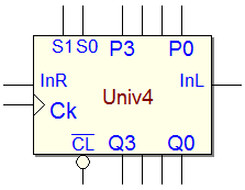
Four bits Universal Register, from the component library of Deeds
6.3 Counters
6.3.1 Binary Counters
T-PET flip-flop, obtained with a D-PET
Four bits counter synthesis, D-PET version
T-PET flip-flop, obtained with a JK-PET
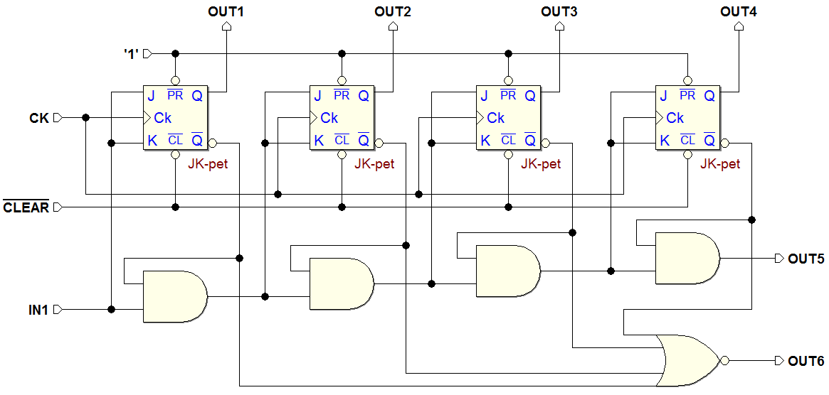
Four bits counter synthesis, JK-PET version
The same one, drawn horizontally
Extensibility of the counter
Four bits Up Counter, from the component library of Deeds
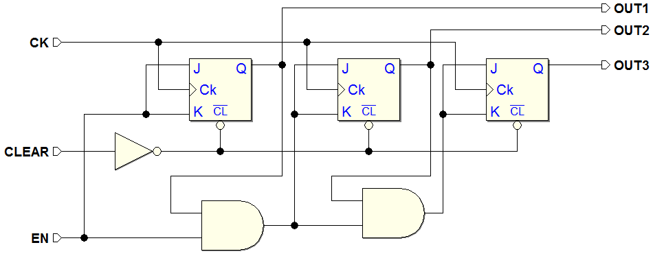
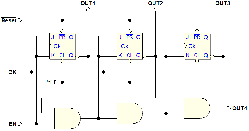
6.3.2 Counters with Enable
Four bits Up Counter, with Enable, from the component library of Deeds
6.3.3 Up/Down Counters
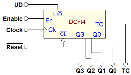
Four bits Up/Down Counter, with Enable, from the component library of Deeds
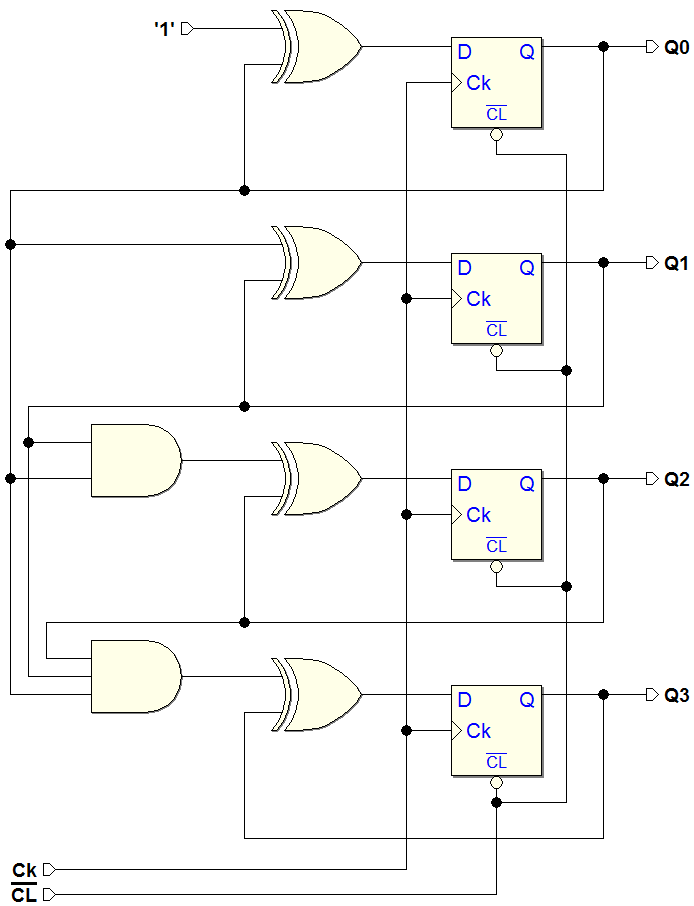
Four bits Up/Down Counter synthesis, D-PET version
6.3.4 "Universal" Counters
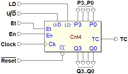
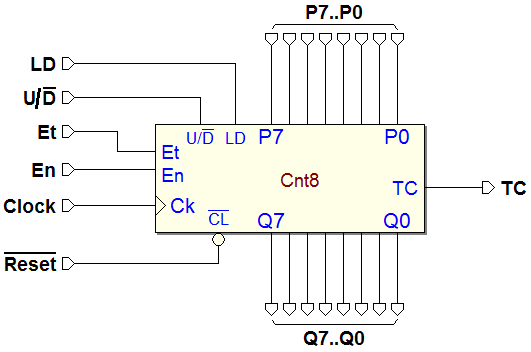
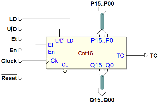
Four bits Universal Counter, from the component library of Deeds
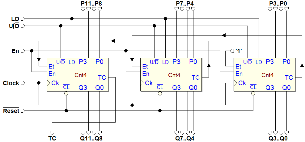
Counter Extension
Examples of Counters, from the component library of Deeds
6.3.5 Asynchronous Counters
Asynchronous Up Counter
Asynchronous Down Counter
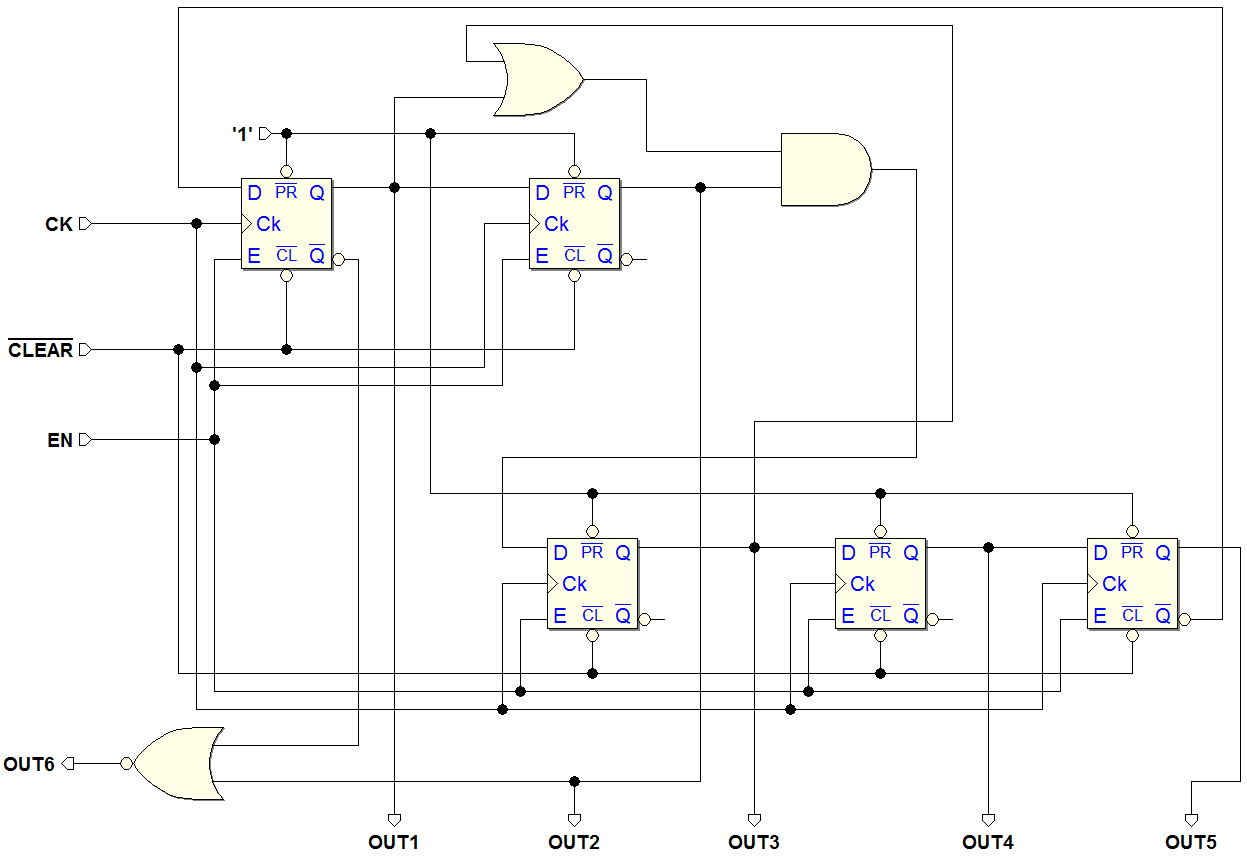
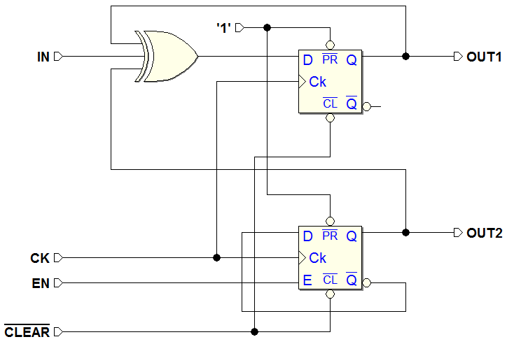
6.4 Network Analysis Examples
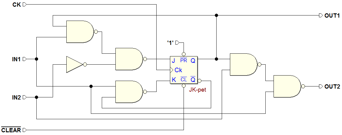
6.4.1 Example 1
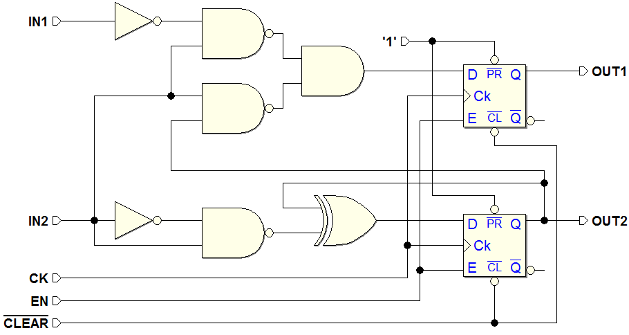
6.4.2 Example 2
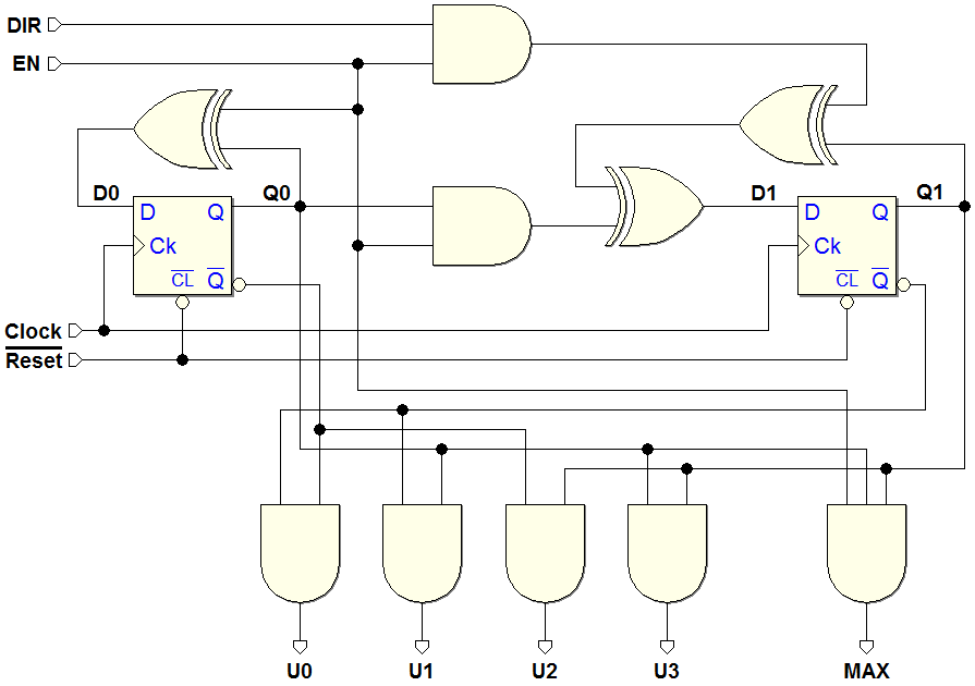
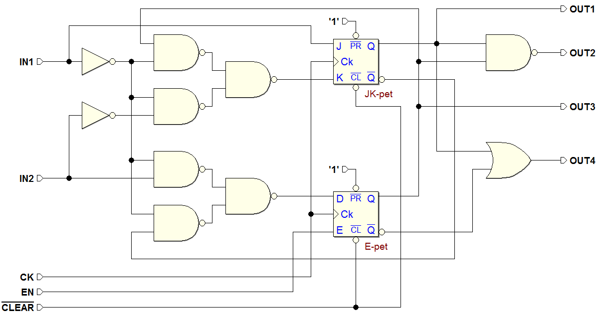
6.4.3 Example 3
Feedback network and output network:
6.4.4 Example 4
Feedback network and output network:
6.4.5 Example 5
Feedback network:
Output network:
6.5 Exercises
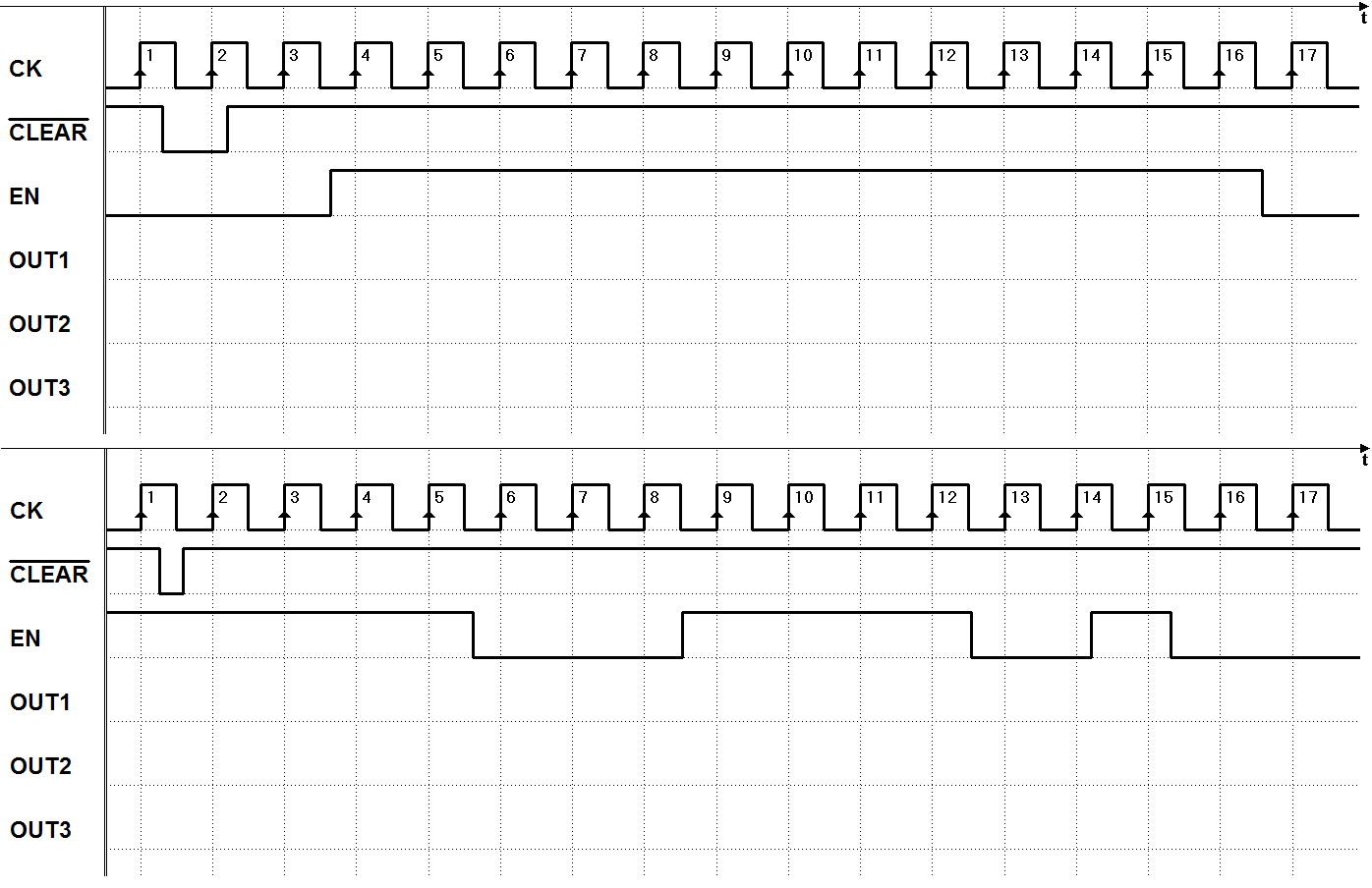
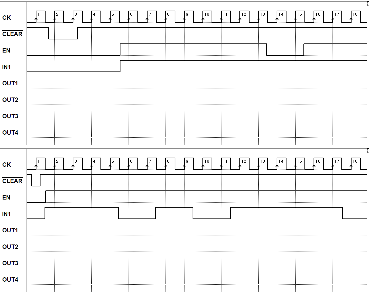
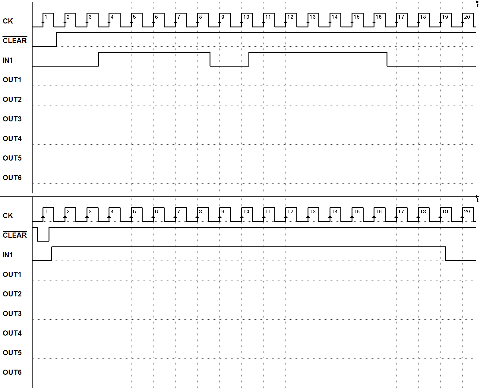
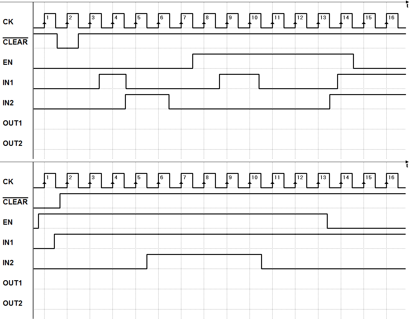
Print the PDF files with the timing diagrams (click on the figure of interest). The time diagrams are the same that appear in the book. They must be completed without the aid of the simulator.
Exercise 1:
Exercise 2:
Exercise 3:
Exercise 4:
Exercise 5:
Exercise 6:
Exercise 7:
Exercise 8:
Exercise 9:
Exercise 10:
6.6 Solutions
The solutions must be verified in the simulator Timing Diagram. In each file (click on the inherent figure) the input sequence is already defined into the Timing Diagram window.
Exercise 1:
Exercise 2:
Exercise 3:
Exercise 4:
Exercise 5:
Exercise 6:
Exercise 7:
Exercise 8:
Exercise 9:
Exercise 10:


