|
|
|||||||||||||||||||||||||||
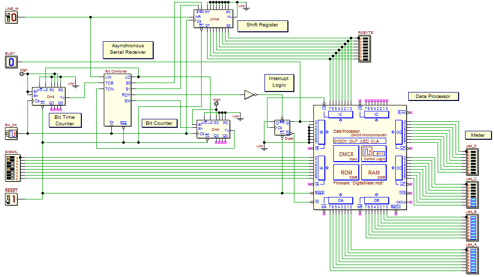
| In this laboratory we'll work on a Digital Meter. The following figure shows its schematic (click on the figure to open the circuit in the editor). The system is based on a DMC8 microcomputer used as data processor, and a serial line receiver. The data processor gets a 8-bits parallel digital SIGNAL on port IA. Then, the digital signal is processed to be represented on the meter display (a 32 LEDs Array), showing the signal level. In the example of the previous figure, the input digital SIGNAL value is 19 (00010011b), and the output LED Array shows 19 contiguous LEDs switched "on" (the other one's "off"). The serial line receiver is connected to the IC input port (the serial line receiver is described here in detail). When the RDY output of the Rx Control presets the D-pet flip-flop, this one activates the microcomputer Interrupt line: a valid serial packet has been received. The microcomputer will read the received byte: the IC port reading operation will clear the interrupt request by loading zero into the flip-flop. The received bits are used by the data processor as parameters to control the decoding of the input digital SIGNAL. Now, we'll write the DMC8 assembly program that realizes the data processor functionalities described in the following. When started, the data processor clears the LEDs array, initializes all the used variables and enables interrupts. Then, in the main loop, the processor will follow the SIGNAL value, updating continuously the output LEDs array. The SIGNAL value is multiplied by a factor, depending from the last packet received from the serial line. Only bit IC0, IC1, IC2 and IC5 of the received byte are significant. IC5 acts as a meter display clear flag: when it is high, all the output LEDs are switched "off". Instead, IC2, IC1 and IC0 code a 3-bits binary number: the factor to be used depends from this number, according to the following table:
Click here to download a trace of a possible solution. When finished to write and test the program in the d-McE, you would load it in the ROM of the microcomputer and simulate the whole circuit in the d-DcS. Note that, to test the receiver, the input "TestSequence" is already available in the timing diagram. | ||||||||||||||||||||||||||||


