|
|
||||||||||
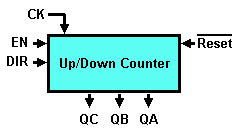
| Design a synchronous mod-5 up/down counter, using the Finite State Machine Simulator (d-FsM). The counter should generate cyclically the sequence from '000' to '100', when counting up, or from '100' to '000', when counting down.
As you see in the figure above:
You can use the ASM diagram template provided, where you'll find the state variables X,Y and Z already defined, as well as the outputs QC, QB and QA, and the inputs DIR and EN. In the template, the codes of five states have been also defined. At the reset, the counter should start from zero. For this reason, the 'a' state is the 'Reset' state (i.e. the 'starting' state of the FSM, at the activation of the asynchronous !Reset). In the template, as it is convenient in the present case, the state codes have been assigned equal to the outputs values (X = QC, Y = QB and Z = QA). Verify, using the timing simulation Once you have finished the FSM design, you can import it in the d-DcS as a component. You can use the d-DcS schematic
template provided, and complete it with the FSM component. Repeat
the simulation of the counter with the d-DcS timing simulator | |||||||||||


 ,
the correct sequence of the output values and the state
codes.
  .
.