|
|
|||||||||||||||||||||||||||||||||||||||||||||||||||||||||||||||||||||||||||||||||||||||||||||||||||||||||||||||||
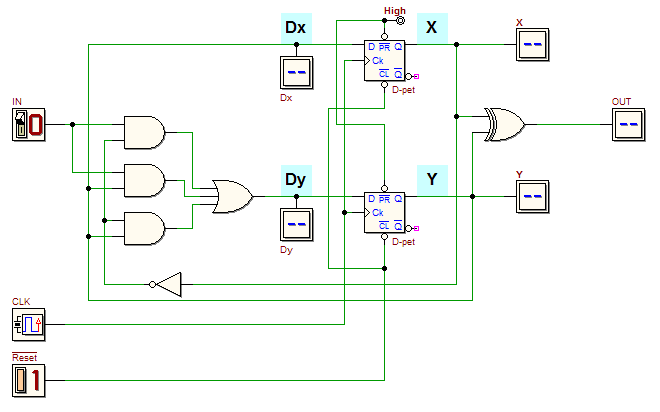
| Consider the following network (click on the figure to open it in the d-DcS): Analyse the network behavior with the timing simulator What kind of relation exists between the input IN and the output OUT? Next, consider it as finite state machine, and obtain the next state and output expressions, defining the outputs Q of the flip-flops as the state variables (X and Y, as in the figure above). Compile a State Table, as the following one, corresponding to the above expressions:
Using the State Table, compile the Karnaugh maps of the output OUT and of the variables Dx and Dy that prepare at the flip-flop input the next state X e Y. Synthesize the network described by the maps and write the AND-OR boolean expression of Dx and Dy. Verify them with the ones obtained before. | ||||||||||||||||||||||||||||||||||||||||||||||||||||||||||||||||||||||||||||||||||||||||||||||||||||||||||||||||||


 (a suitable test sequence is available in the Timing Diagram window).