Programming ROM components
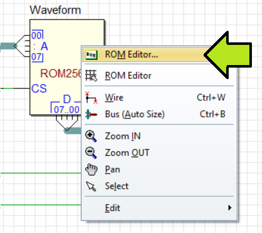
The ROM components can be programmed in multiple modes. This includes the ability to initialize the memory with a sampled waveform. The user can launch the ROM Editor/Programmer from the component's context menu, as shown in the example.
The ROM Editor/Programmer dialog allows you to directly edit memory contents in Binary, Hexadecimal or ASCII text format. You can use the Undo/Redo buttons to reverse any changes. To edit a memory cell, simply click on it, and to move to the next cell, press the right arrow key.
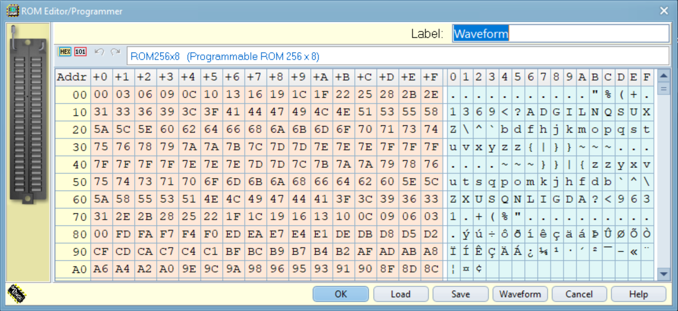
The Label field, where users can enter a symbolic name for the memory component, is an edit field located in the upper right side of the dialog. The dialog also includes three buttons (Load, Save, Waveform).
Utility for Generating Waveforms
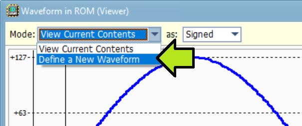
Clicking on the Waveform button opens the 'Waveform in ROM' dialog in Viewer Mode. The dialog displays the Rom data as a digital signal in a two-dimensional chart, as shown below. The horizontal axis represents the internal addresses of the memory, and the vertical axis represents the corresponding data values. In this example, the memory contains the 8-bit samples of a complete sine wave cycle, coded as signed binary numbers.
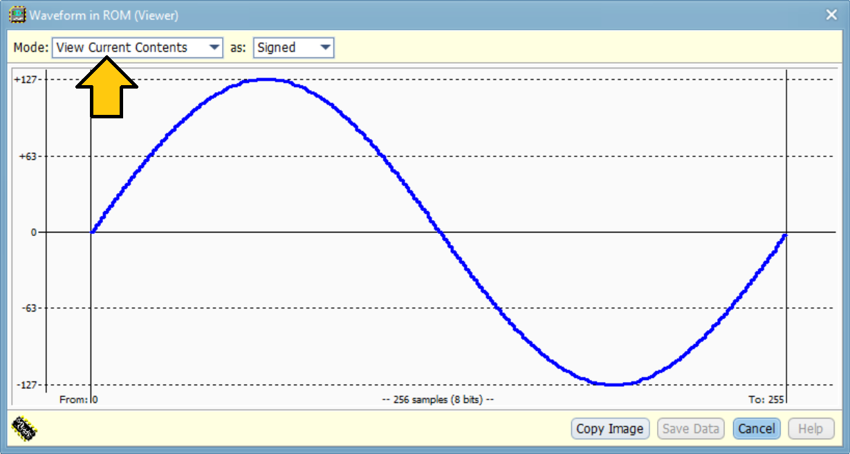
To change the waveform, you must first change the mode (see the figure below).
Now, a new waveform can be selected from the Wave list box (see below).
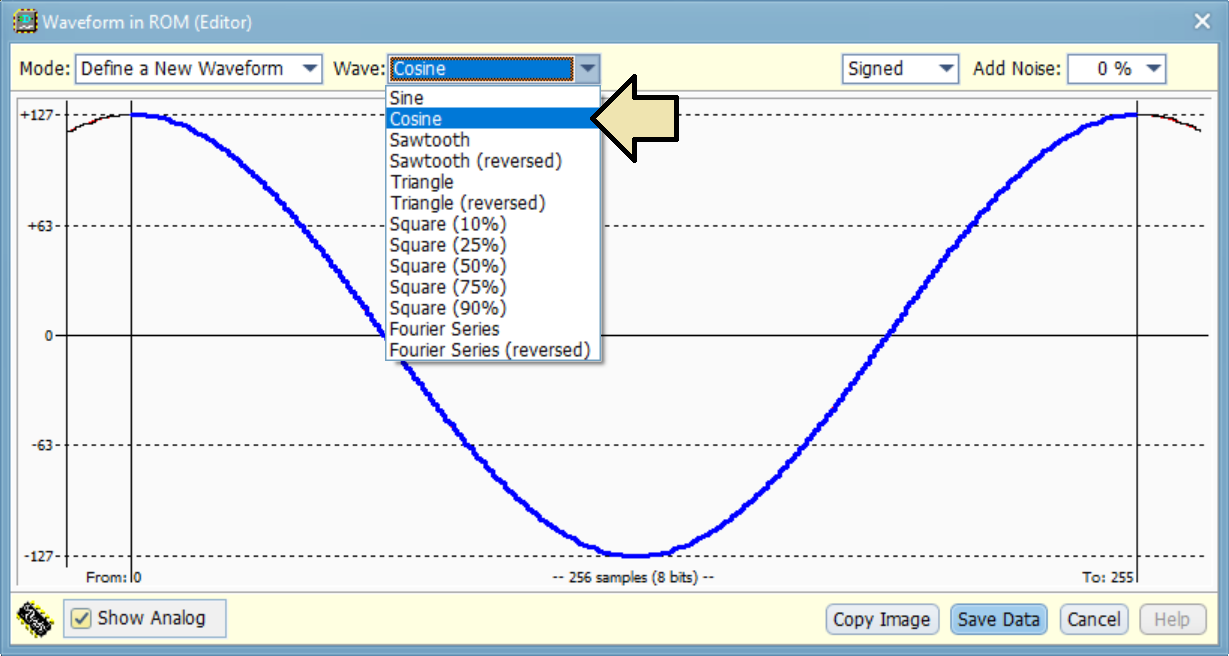
The user has the option to select a standard function, which includes sine, cosine, saw-tooth, triangle and square wave. In the figure above, the cosine waveform is displayed. The waveform samples are calculated to memorize a full cycle of the wave and to reach the highest possible amplitude, which is centered on zero if signed (from +127 to -127, as in the figure above), or all-positive (unsigned, from 0 to 254).
The 'Copy Image' button allows you to copy the waveform image to the clipboard, so you can paste it into your document.
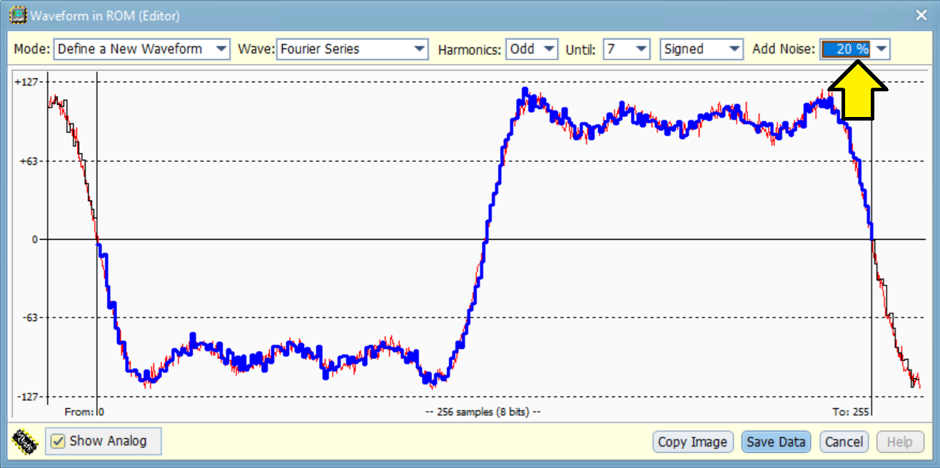
The Fourier Series utility, a mathematical method representing a periodic function as a sum of sine waves, is located at the end of the waveform list. It offers a choice between two classic series (square wave and saw-tooth wave), and the series can be stopped at a given order. In the example below, the square wave series is set, and limited at the seventh harmonic (since only the 'Odd' harmonics have been selected).

Clicking on the desired sample will open the Waveform Magnifier window (see below).
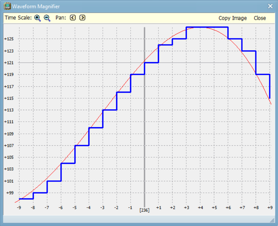
This image presents a magnified view of the waveform detail from the previous figure, centered around sample address 236, which has a value of +121. The digitized waveform is displayed in blue, and the original analog waveform that was sampled is shown in red.
Control buttons are provided to adjust the time scale and horizontal panning. The vertical scale is adaptive. Additionally, a 'Copy Image' button allows users to copy the waveform image to the clipboard.
The image below demonstrates how to add white noise to the waveform within the Waveform Editor.
The figure below displays a waveform generator with its ROM loaded with the last waveform examined. Click on the figure to open the circuit in Deeds-DcS.

The video below provides an animated demonstration of the simulation. The full resolution version can be downloaded here.
Details on using the DSO can be found here.
Data Import and Export
Going back to the ROM Editor/Programmer dialog, let's look at the Load and Save buttons.

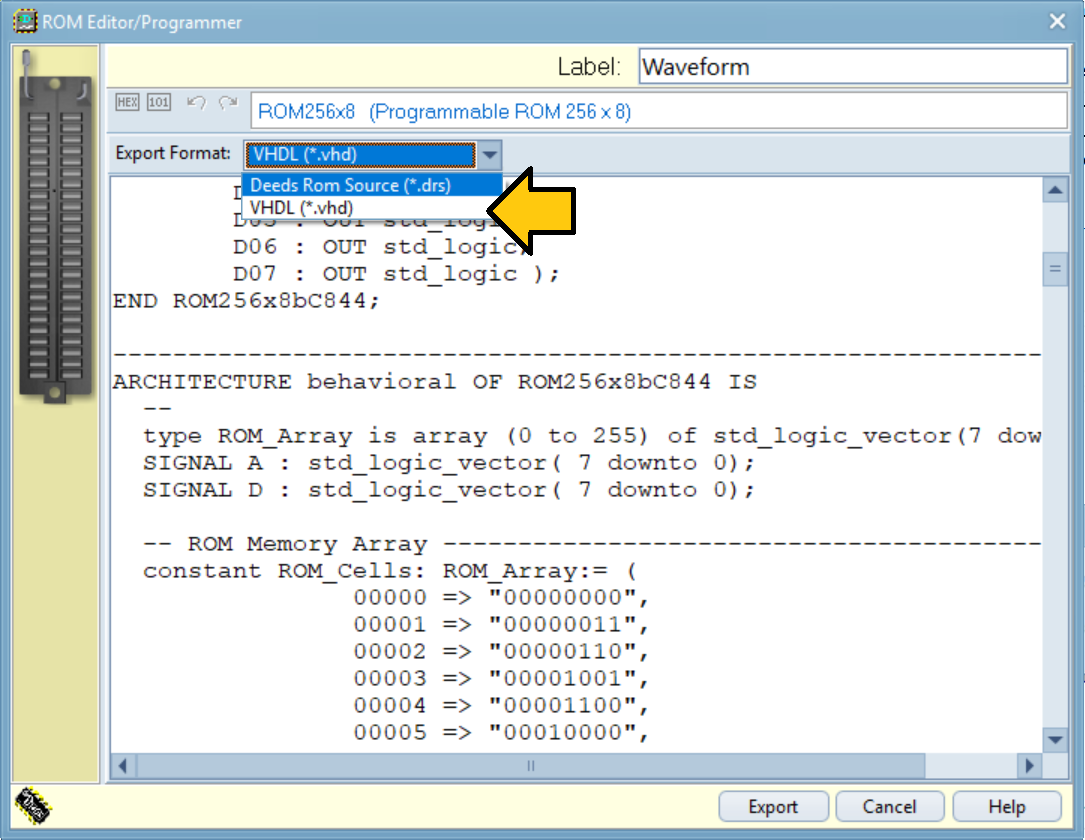
The contents of the ROM memory can be saved to and loaded from a coded text file. The code is displayed in a dialog box before it is saved. Clicking the 'Save' button changes the dialog's appearance and enters export mode (see below). The default file format for saving is '.drs' (Deeds Rom Source file).
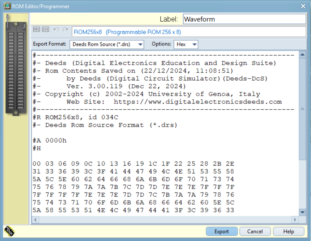
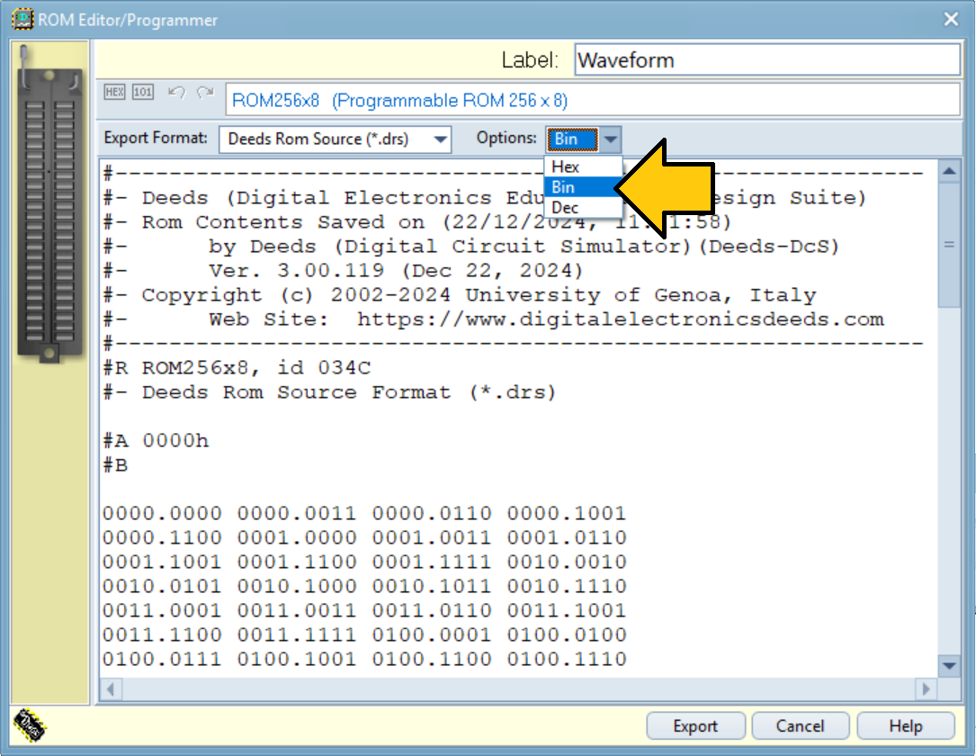
The example above shows data formatted in hexadecimal, while the example below shows data formatted in binary. As shown, we can choose how to encode the exported data (hexadecimal, binary or decimal).
Clicking the Export button opens a 'Save As' dialog. The dialog closes after saving the file. Export mode can also be exited by pressing the Cancel button or the Escape key.
DRS File Format
A .drs files can be opened and modified using a simple text editor. Click the 'Load' button to import and compile a .drs file. The data from the file is then used to program the ROM component.
In the example below, a hash symbol (#) followed by a dash (-) at the beginning of a line denotes a comment, while a hash symbol followed by a letter signifies a directive. The hexadecimal numbers on lines without a hash symbol at the start represent the data contents of the ROM, organized by memory location.
#- Deeds (Digital Electronics Education and Design Suite)
#- … omissis …
#-----------------------------------------------------------
#R ROM256x8, id 02F0
#A 0000h
#H ;
4E 65 6C 20 6D 65 7A 7A 6F 20 64 65 6C 20 63 61
6D 6D 69 6E 20 64 69 20 6E 6F 73 74 72 61 20 76
69 74 61 20 6D 69 20 72 69 74 72 6F 76 61 69 20
… omissis …
A directive must be always written in the first position of the line, and can be one of the following.
#R ROM256x16, id 0004 Rom component Type (ignored at compile time);
#A <address> Start address of data that will follow (hex or decimal),
if no #A directive is defined, the default address is zero;
#T "Text contents follow", that is read starting from the next
line (including CR/LF), and stored from the address defined
[this is the default];
#H Declares that the following numbers are hex;
#B Declares that the following numbers are binary;
#D Declares that the following numbers are decimal.
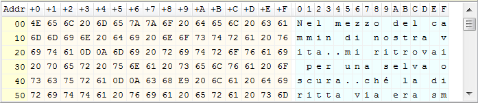
The example file contains code that will load the opening lines of Dante Alighieri's epic poem, the 'Divina Commedia', into memory. The directives in the file are optional and could be removed, leaving only the text of the poem.
#- Dante Alighieri
#-----------------------------------------------------------
#A 0000h
#T
Nel mezzo del cammin di nostra vita
mi ritrovai per una selva oscura
ché la diritta via era smarrita.
Ahi quanto a dir qual era è cosa dura
esta selva selvaggia e aspra e forte
che nel pensier rinova la paura!
The content that is produced will be displayed in the ROM editor grid (refer to the following image).
VHDL Generation
The VHDL code for the ROM component, along with the data, can be generated.