 Attenuator Components
The image below displays the menu options for adding attenuator components to the schematic.
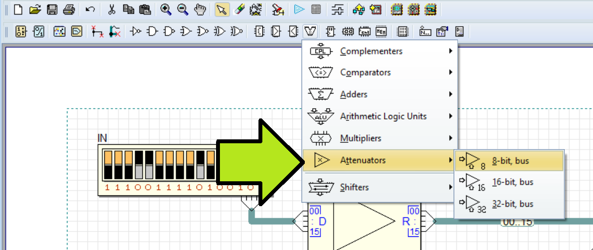
The following components, each with a distinct bit size, are available.
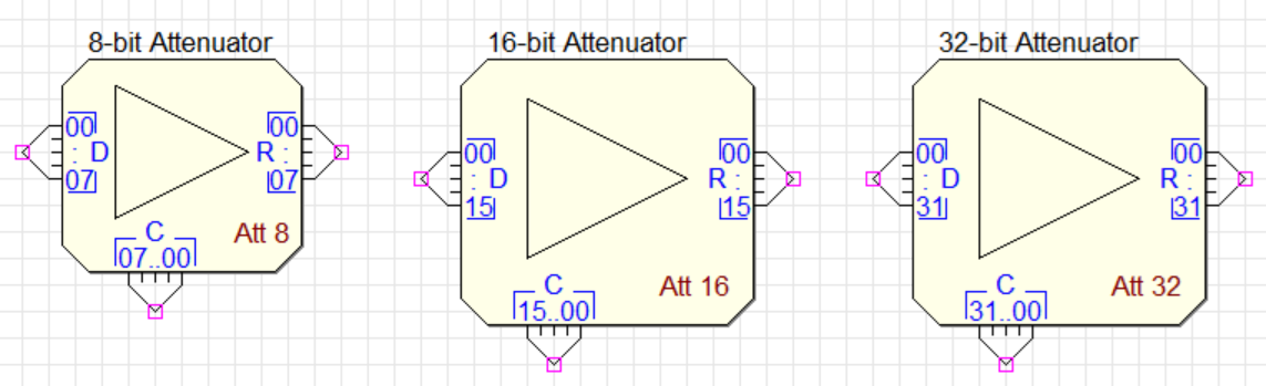
The three components work with 8-, 16- and 32-bit signed numbers (encoded in two's complement), respectively. D (Data) is the input, R (Result) the output. The two components are graphically similar except for the overall dimensions and the bus pin size. C (coefficient) is the control parameter. These three components operate according to the following relation:

Where C is an unsigned fixed-point number, with the binary point set just after the first bit on the left. Therefore, its decimal value ranges from 0.0 to 1.0, as any number exceeding 1.0 is automatically adjusted to 1.0.
Basic example
The following image displays a basic test circuit for the 16-bit type attenuator. To open the circuit in Deeds-DcS, in Auto-Play Mode, simply click on the image.

The figure illustrates an example where the input D receives the binary signed number '1110011110100100' (equivalent to -6236 in decimal). At the same time, the control input C is set to '0.100000000000000' (equivalent to 0.5 in decimal). As a result, the output R is '1111001111010010' (-3118 in decimal), which is half of the input value.
Low Pass Filter example
The following image depicts a first order low pass digital filter, built using two 16-bit Attenuator components, a 16-bit adder, and a parallel register. Click on the figure to open it in the Deeds-DcS (in Auto-Play Mode).

To start testing the circuit, wait for the automatic reset to finish activating. Immediately afterward, observe how the output increases exponentially from zero. Next, click the 'INPUT' switch on the left side of the schematic to toggle the input between the minimum and maximum values. Repeat this process, flipping the switch state multiple times to observe the effects on the circuit output.
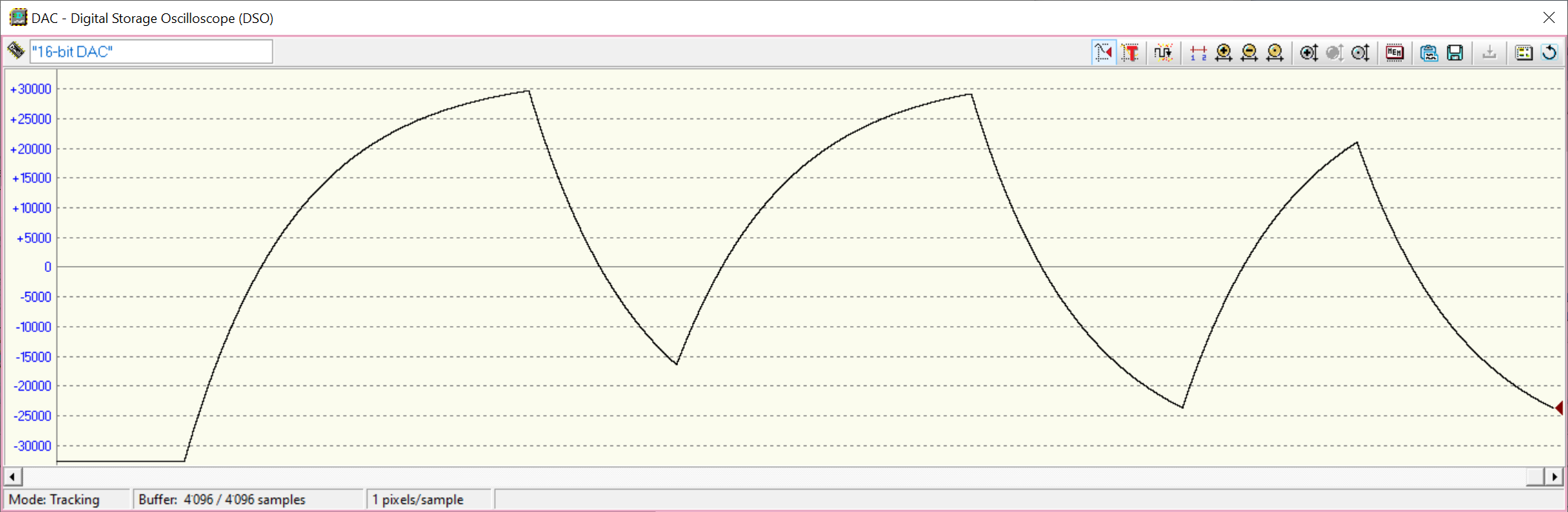
A timing diagram, similar to the one shown below, will be displayed on the Digital Storage Oscilloscope. To open the Oscilloscope, click on the DAC16 component with the mouse during the simulation.
Low Pass Filter extended example
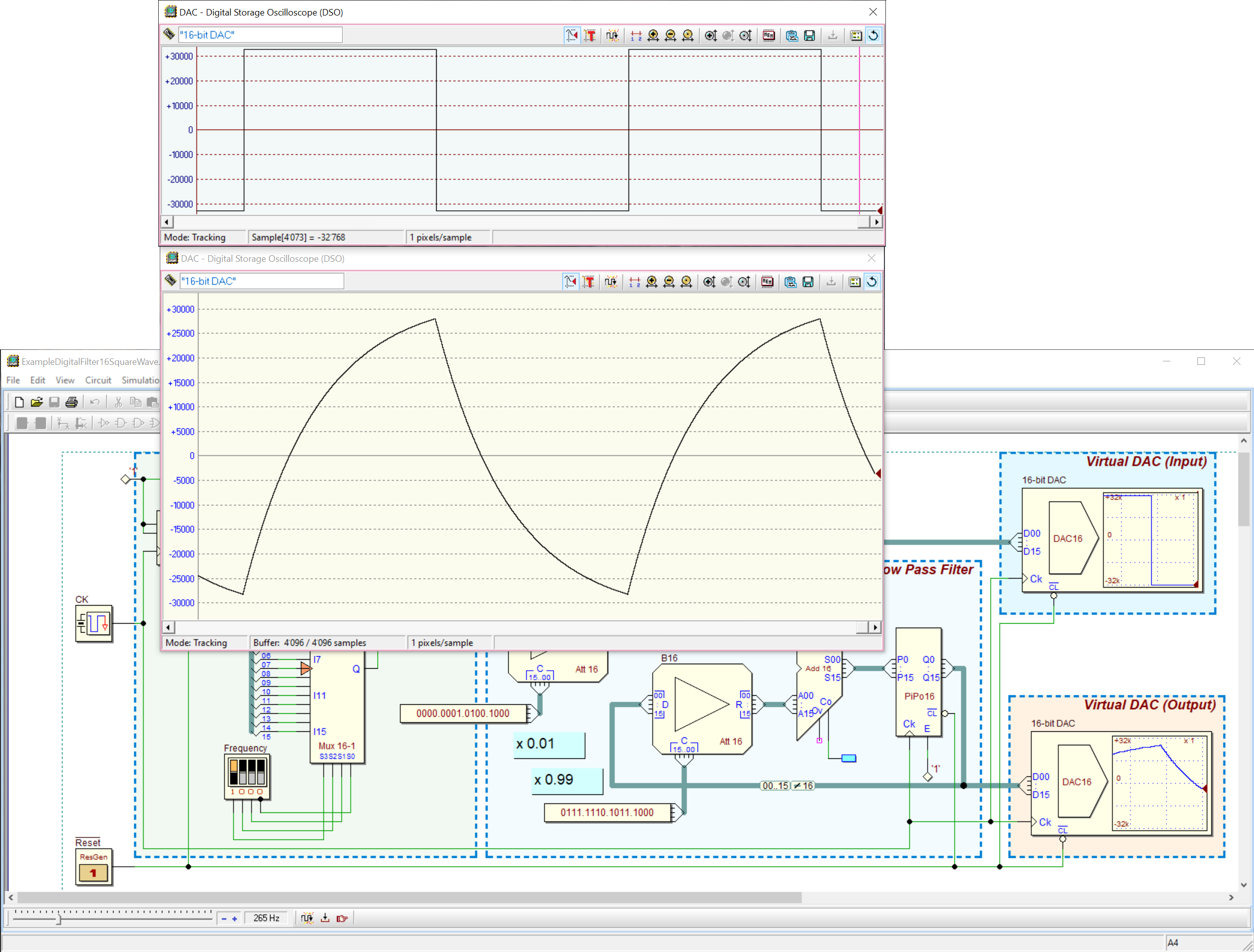
The frequency of the square wave generator, which drives the same filter, can be controlled through the 4 switch array labeled 'Frequency' in the following figure. To open the figure in the Deeds-DcS (in Auto-Play Mode), click on it.

To analyze the correlation between input and output waves, you can open and configure the Digital Storage Oscilloscopes of the DAC16 components by clicking on them during the simulation. The image below shows an example of a comprehensive window setup that can be used for this purpose.
The animated simulation is demonstrated in the following video, which can be downloaded in full resolution here. In the video, the frequency of the square wave at the filter input is progressively increased by the user. As a result, the amplitude of the filtered waveform at the output is correspondingly reduced.
The description of the use of the DSO can be found here.