|
|
|||||||||
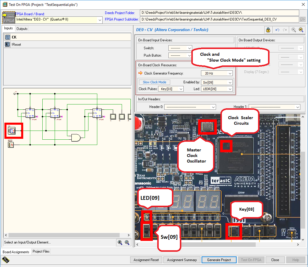
| Before continuing, you should have read the page: In this page we show the features offered by the DEEDS for testing sequential networks on a FPGA board Terasic/Altera DE0-CV. We choose, as working example, a simple 3-bit binary counter, of which we have designed the structure (a click on the figure will open the schematic on the Deeds-DcS): It is useful to test the network both in the animation To implement the counter on the DE0-CV board, open in the Deeds-DcS the dialog window shown in the figure below, using the command “Test on FPGA”. In this example, all the associations between the schematic and the corresponding input/output devices on the DE0-CV are already set.
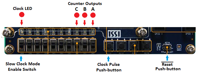
The figure highlights the association of the network’s clock with the DE0-CV devices. Clock frequency has been set very low (20 Hz), to allow a visual control of the counter, whose outputs are connected to three green LED on the board. The “Slow Clock Mode” has been enabled, assigning to the switch Sw[09] the task to activate it at runtime. It has been selected a LED, LEDR[09], to visualize the clock pulses being sent to the circuit. Finally, the pushbutton Key[03] has been chosen to control the manual generation of clock pulses (instead of selecting a pushbutton, the user could choose a continuous sequence of pulses, from one pulse every ten seconds to five pulses per second). If Sw[09] is at '0', the Slow Clock Mode is not active and the clock is the "normal" (20 Hz). If Sw[09] is turned on at '1', the system stops clock generation and waits for the user to press Key[03]. Each activation generates a clock pulse (a rising edge corresponding to the pressing, followed by a falling edge at release). LEDR[09] will light on the high level of each pulse (a useful feature to highlight visually clock edges). A long pressure produces a continuous generation of pulses (approximately two per second). The following figure shows a comprehensive view of the associations and it can be seen as the “control panel” of our system: |
||||||||||


 and timing
  simulation modes of the Deeds-DcS. A proper test sequence is available in the timing simulation window. We recommend to avoid any change on the schematic about the input/output terminations, already defined for exporting the project on the FPGA board.
