Synchronous Serial Communication System (4 bits)
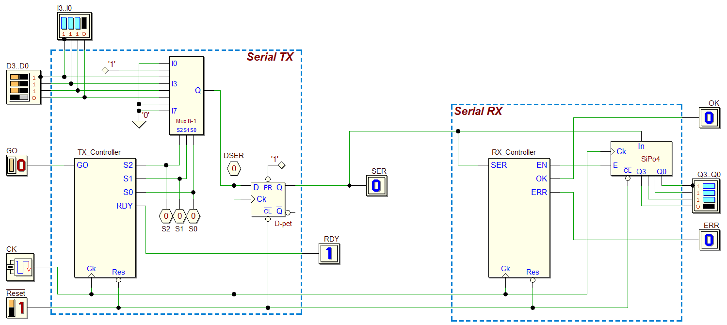
In this example, starting from the two previous projects (Serial Transmitter, Serial Receiver), we’ll connect the TX and RX modules to obtain a complete (even if simplified) Synchronous Serial Communication System:

The TX unit reads a 4-bits parallel data (D3…D0); when the input GO goes from 0 to 1, data is serialized and transmitted on the line SER, in the format of a serial packet, as in the following figure:

- The bit sequence is synchronous with the clock CK;
- The bit time duration is equal to one clock cycle;
- Each sequence begins with a Start Bit (high);
- Four data bits follow (D0, D1, D2 and then D3);
- The bit packet ends with a Stop Bit (low).
For the TX operation details, consider refer to the Serial Transmitter project. The 4-bits synchronous serial receiver reads the sequences from the line SER, and generates the outputs Q0, Q1, Q2, Q3, OK and ERR. For the specifications, see the Serial Receiver project.
Solution
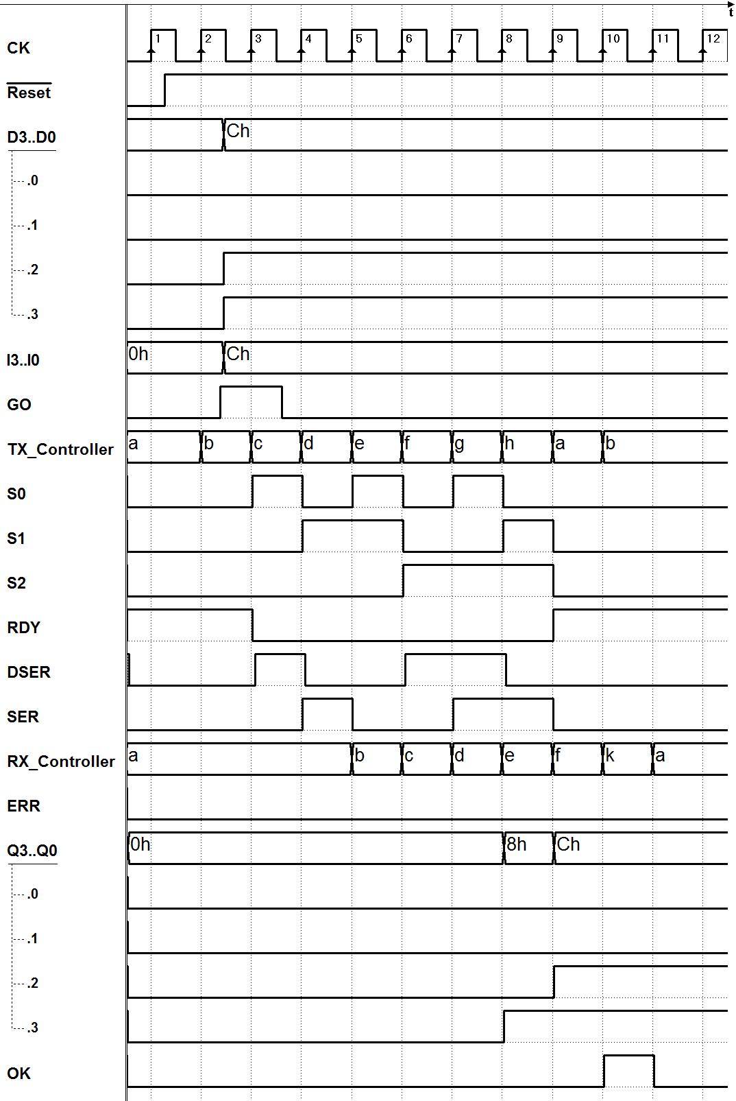
We set the 4-bits data D3…D0 on the TX side, and then activate GO. After a time, depending on the clock frequency, that data bits will be replicated (and maintained) on the output Q3..Q0. The activation of OK will signal that new data is available. To do that, we simply connect together the circuits of the TX and RX as (a click on the figure will open the circuit in the Deeds-DcS):
Here the timing simulation:

