 ASM Diagrams and State Diagrams ASM Diagrams and State Diagrams
In this context, we present some examples that compare the "ASM Diagrams" in the Deeds-FsM tool with the more widely known and common "State Diagrams".
Despite their different names, these diagrams are quite similar because both ASM Diagrams and State Diagrams portray the state-to-state transitions and outputs of a machine.
In order to facilitate the use of ASM Diagrams, we will utilize examples provided in Appendix B of the book Introduction to Digital System Design. These examples demonstrate the conversion process between ASM Diagrams and State Diagrams. Refer to the figure below for a visual representation of this process.

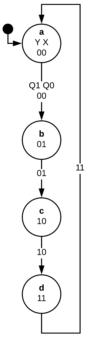
To illustrate, we present a module-4 counter example described using an ASM Diagram on the left. The states are represented as rectangles, where the active outputs in a particular state are displayed within the rectangle and the state binary code is indicated at the top right corner. Arrows connecting the rectangles represent transitions from one state to the next.
On the right, the corresponding State Diagram is depicted. Circles (or bubbles) represent states. Lines (arcs) with arrows connect the states, indicating the transition direction. In either diagram, each state is denoted by a letter: (a), (b), (c) and (d). Each circle in the State Diagram additionally contains the corresponding binary code. The lines are annotated with Q1 Q0 output values. For Moore machines, the outputs can also be written inside the state circles.
In ASM Diagrams, input variables that affect state transitions are shown within Decision Blocks.
For example, consider the bidirectional counter in the figure below. The input DIR controls the counting direction: DIR = 1 increases the count, and DIR = 0 decreases the count.

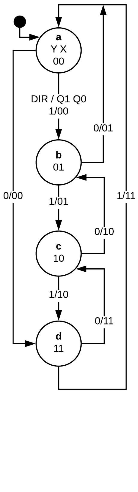
In the ASM Diagram, decision blocks are used to define logical paths that lead to different states. The input value determining the path is indicated next to the exiting line.
In the corresponding State Diagram, each state has two exiting lines. The DIR input is written on the lines before the slash, and the pair of digits following the slash denotes the outputs, similar to the previous case.
In a Mealy machine, like an Edge Detector with conditional outputs, the output values are dependent on both the current state and the input values. The figure below provides a visual representation of this relationship.

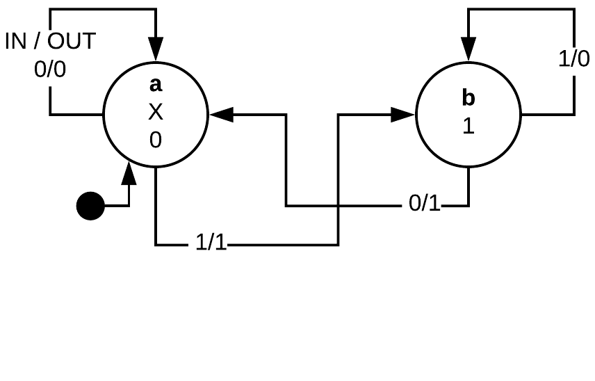
In the ASM diagram, a rectangle with rounded corners signals a Conditional Output. In state (a), output OUT activates if IN = 1, as illustrated by the diagram.
In the State Diagram, like in the previous scenario, values of outputs follow the slash. However, these values vary with the input values.