 Linear Gauge Components
A Linear Gauge, similar to a progress bar or a column of LEDs, presents output data in an analog format (click on the figure below to open the circuit in Deeds-DcS).

The animation below simulates the circuit. Download the full resolution version here.
Resembling a ruler with notches, these components display a numerical value rather than a full scale. Only a zero point (which can be centered or placed at an extreme) is marked on the scale to maintain clarity. These Linear Gauge components, available in both 4 and 8-bit versions, can be found in the output components group, as shown in the next figure.
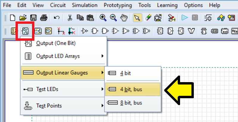
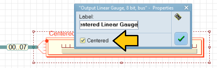
The properties dialog allows you to specify the position of the zero; whether it should be centered or off-center.
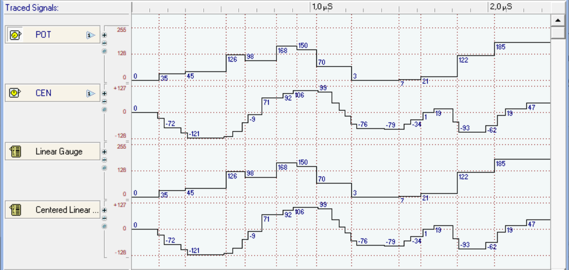
The linear gauges within the timing diagram, displayed in 'pseudo-analog' mode, closely resemble and function similarly to digital-to-analog converters (DACs), representing the output.
VHDL code is not generated or exported from Linear Gauges, as they are designed exclusively for simulation purposes.