 Led Matrix Display components
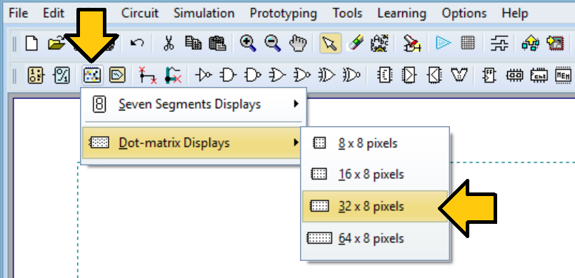
The menu options for adding a Led Matrix Display component to the schematic are shown in the image below.
The following figure shows the four different available components.
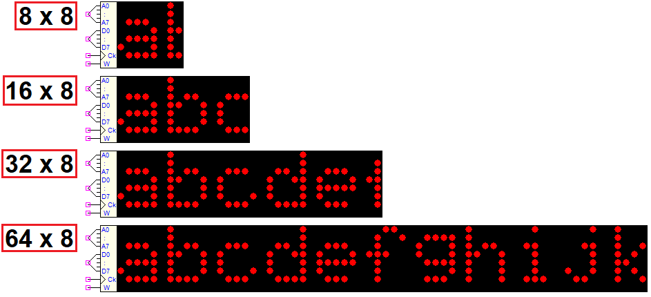
While data can only be written and not read, these components function similarly to RAM memories. The following figure illustrates that all types of LED Matrix Displays share the same pinout, regardless of the number of columns.

The Address Bus (A7..A0, 8-bit) determines the column to be written. The default setting is for the leftmost column to have the first address (0), then the addresses increment from left to right. This default can be changed by assigning a non-zero address offset so that the columns (8, 16, 32, or 64) align with a specific memory area. Additionally, the relationship between addresses and columns can be horizontally inverted to mirror the image.
The 8-bit Data Bus (D7..D0) is used to write the desired dot pattern in the chosen column. D0 represents the top pixel by default, while D7 represents the bottom pixel. Later in this document, we will detail how to reverse this default correspondence (to flip the image vertically).
The data D7..D0 is written into the chosen memory location on the positive edge of the Write Clock, by activating Write Enable input (W).
LED Matrix Properties Dialog Window
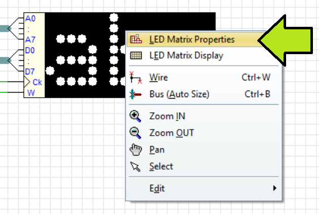
The properties of a component can be adjusted after insertion, or at a later time, by double-clicking on the component itself, or by accessing its context menu as shown in the following image.
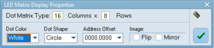
The next figure displays the default settings in the dialog window. The upper portion of the dialog box displays the number of rows and columns for the specific component type that was inserted; this cannot be edited.
The component's appearance will reflect the immediate changes made to the options, and these changes can be observed interactively in the dialog.
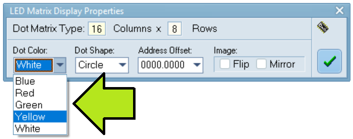
The following image displays the available color options for the pixels. The display is monochrome, so the selected color will be applied to all pixels within the matrix. (Remember that the background color is always black and cannot be changed.)
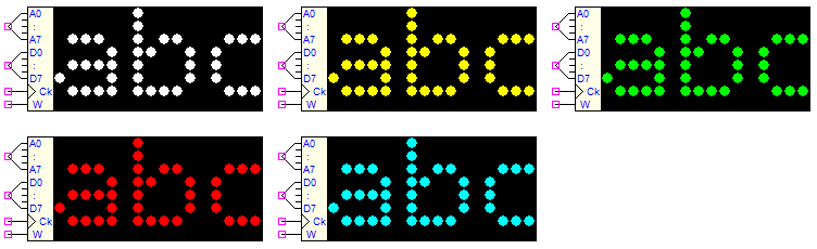
The following are examples that vary based on the chosen dot color.
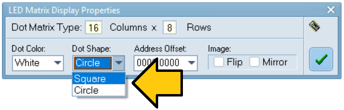
The two shapes that are available for the pixels, Square and Circle, are shown in the following figure.
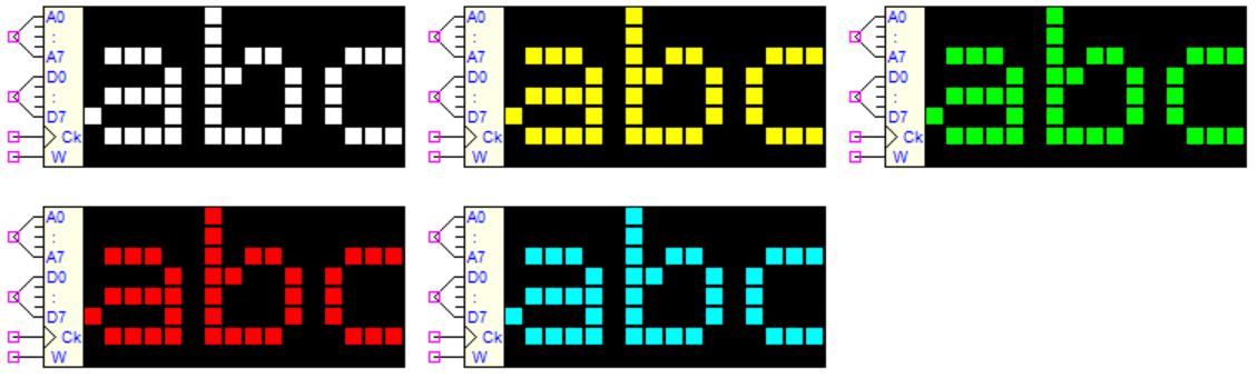
The same illustration is shown here, but with all pixels changed to Square.
As mentioned previously, the Flip and Mirror commands can be used to invert the pixels in both directions if needed. The demo image below has both commands set, resulting in a vertically flipped and horizontally mirrored image.
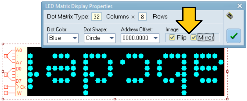
The display of the initial letters of the alphabet is an illustrative feature that allows for the interactive observation of property changes when the circuit is being edited.
Combine multiple displays together
The illustrative circuit demonstrates how multiple displays can be joined to create a larger display. By connecting four 64x8 dot displays vertically, a single 64x32 pixel display is formed (click on the image to open the schematic in the Deeds-DcS).

The schematic shows that all input connections have been paralleled. This circuit uses a counter to load each memory location with a bit configuration that matches its memory address. To achieve this, it was necessary to modify the Address Offset property for each component, as illustrated in the figure below for the bottom device.
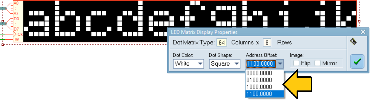
The initial Address Offset at the top retains its default value '0000.0000', while the subsequent three are assigned '0100.0000', '1000.0000', and '1100.0000', respectively. This configuration allocates successive and continuous memory areas to each display, effectively creating a single 256-location memory buffer. The available Address Offset options are influenced by the size of the component matrix.
- 8x8 matrix: 32 possible areas (8 locations each)
- 16x8 matrix: 16 possible areas (16 locations each)
- 32x8 matrix: 8 possible areas (32 locations each)
- 64x8 matrix: 4 possible areas (64 locations each).
Scrolling banner example
The classic message "Hello World!" is displayed as a scrolling banner in this example using a DMC8 Microcomputer.
Two Led Matrix Displays (64x8 dots) were positioned side-by-side horizontally. The right display was rotated 180 degrees, and both Flip and Mirror controls were enabled in its property window to ensure the string was continuous with the other display. Additionally, its Address Offset was configured to '0100.0000' to drive the two displays as a single unit, and a distinct dot color was selected (click on the figure to open it in the Deeds-DcS).

The animated simulation is demonstrated in the following video, which can be downloaded in full resolution here.
The Deeds-McE allows users to open and view the assembly code for this example.